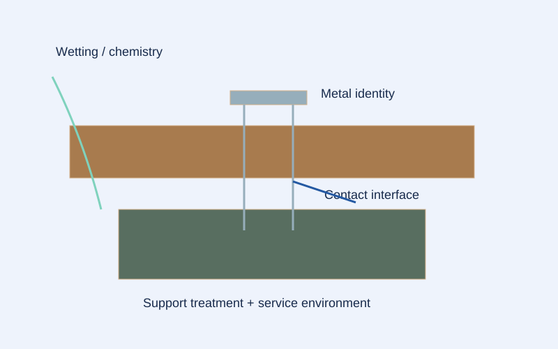
- Identify each metal and the exact support treatment.
- Wetting and chemistry act at the contact interfaces, including sheltered locations.
- The diagram maps questions, not a grade recommendation or corrosion service-life estimate.
List metals without guessing
Create a material schedule for the screw, clip, connector, washer, flashing, rail fitting, and other nearby metal parts. Record documented alloy or coating information and mark uncertain identities plainly. Appearance alone is not enough to distinguish many finishes. Photograph component labels before packaging disappears and connect each entry to its location in the assembly.
Draw the contact paths
Use a section sketch to show where parts touch and where water may be present. Include concealed screw shanks and the edges of washers, not just broad exposed faces. FEMA warns about joining dissimilar metals in coastal guidance. That principle is a reason to review the actual combination, not a standalone table that certifies every mixed-metal detail.
Evaluate the proposed separation
If isolation is part of the design, identify the exact separation material and how it continues around fasteners, cut edges, and terminations. Ask whether the installation sequence can maintain the specified separation. A sketch with a generic line labeled barrier leaves essential questions unanswered. Keep maintenance and replaceability in the discussion when the layer will become inaccessible.
Control substitutions as combinations
A substitute connector may change more than its shape. Require its material and coating to be compared with the approved connector and adjacent hardware. Present the full revised combination to the responsible reviewer. Do not approve a component in isolation and assume the previously accepted assembly remains accepted after its contacting material has changed.
Inspect before hiding the interface
Use a planned inspection point to photograph actual parts and separation details before they are covered. Record visible damage, missing layers, or a different washer without assigning a corrosion rate. Resolve discrepancies against the approved detail. Store the images with the component schedule so a future investigator can understand what was installed without relying on memory.
Practical checklist
- Identify metals and coatings for every component.
- Show concealed contacts in a section sketch.
- Document continuity of any specified separation.
- Review substitutions as a complete combination.
Worked example
Hypothetical example: an approved screw is paired on site with a newly substituted metal trim. The contact schedule exposes the change, and the team obtains a revised interface detail before concealment rather than assuming the screw approval covers the trim.
Limits of this guide
A contact map is not an electrochemical calculation or engineering acceptance. It cannot predict corrosion life. Separation measures must be suitable for the actual assembly; do not improvise a barrier and claim it eliminates every contact mechanism.
Continue the decision
Review fasteners against the actual treated support
Specify stainless fasteners with evidence beyond the label
Submit the connection as one coordinated assembly
Connection worksheet